Sunday, June 3, 2012

Postscript

Well its been a couple of years since the last post. What happened? Basically 1/ I gained access to a very nice Phantom 380; 2/ there was an interesting set of posts on the LBWS site which laid out the design for a wave-piercing skiff board. This design was subsequently (or maybe in parallel) commercialised in the Exocet RS D2 board. No real point in building a Phantom-like board when one is already available to sail, and when a new more innovative design is sitting in the wings. Thus it is better to wait and see how the skiff board design pans out before playing around with a similar design.

So life is good with the Phantom, coupled with a bunch of Tushingham race sails.


The fitness has slowly been building and so the opportunity to carry big sails in stronger winds continues to expand. In this regard, a real buzz this year was sailing the the Breakwater to Beacon race- huge fun although I finished well towards the back!

Anyway, good luck with the future and keep sailboarding!

All the best.

Martin


Wednesday, March 24, 2010

Closing In

Well it has been a great summer here for sailboarding. As always I am torn between finalising the longboard design and beginning construction, and doing some sailboarding on the bay and building some fitness. In fact the latter has won out the last few weeks- I've started racing the venerable Tiga around the course with the dinghy's at Elwood- great fun except that- boy are those running legs are a pain in the bum when the sea is sloppy and the wind is too light to make it worth tacking downwind. Still sailing the Tiga is good training as it is a relatively narrow board and so mastering the transitions (and sailing directly downwind) is good practise for racing the longboard (bit like limbering up with a weighted baseball bat before going out to face the music on the diamond.

Nevertheless, I have still been making progress with the construction table now completed and levelled as shown above plus I've put together some data on the relative location of the components on a longboard. This is shown in the plots below where the normalised distance of each component from the board has been plotted for three different longboards and the Tiga. 
First of all it can be seen that there is a reasonable degree of consistency between the boards in terms of where each component is located. For example it can be seen that the fin is typically located about 5% of the board length forward from the tail; the downwind/reaching centre strap is about 7% forward of the tail/ the centreboard pivot point is about 35% forward; and the mast track extends from about 40% to 55-60% forward of the stern.

So this is all good news. I have now have consistent models for board rocker, board plan view, board thickness and component location. Finalisation of the design is now very close.

And finally, my kids are getting in on the act now too. The attached clip shows my oldest son working hard to wreck the Elwood boating pier.

All the best- Martin

Saturday, January 23, 2010

Holidays

Hi Blogosphere, back after a trip to the south of France (massive cold snap, and the interesting experience of piloting a left-hand drive car in snow and ice down narrow country roads with all of those wild rural French drivers; not to mention being attacked by a massive bloody sanglier after being stuck somewhere up an icy mountain road in the dark...). Anyway, that's another story. It was such as contrast to get home here to Melbourne, Australia where the temperature was 25C (rather than -8C); to be able to wear shorts and a tshirt again, and to be able to go sailboarding- currently without the need to wear a wetsuit.

Speaking of sailboarding. Shown here is the rig that I'll initially be using on the longboard (thanks Jack for the 'loan'). Severne Code Red 8.3m^2; Hypersonic 75% 490cm mast; Chinook Triple Course boom; Pro Limit 45cm Ext. It's a big change from the 5.7m2 sail that I've previously been using. The Severne has so much more power plus flexibility to handle a wide range of wind speeds. I was out sailing yesterday on my old Tiga 325 with the new rig- in 12-15 knts, what a buzz!

Since returning from our holiday, I've commenced working again on the sailboard construction bench. So this is the build that you have to have before doing the real build- the sailboard itself.
In this regard, I've been thinking a little more about how best to cover the foam core. After sailing at Elwood yesterday, I was able to get a close up look at a Phantom 380, and boy does it look fragile. A beautiful board, but clearly (in my opinion), longetivity has been traided off against lightness, and I guess, speed. This issue was nicely summarised on the Longboard Windsurfing Journal and it really suggests that a pure carbon fibre skin may not be the way to go with these boards, unless that is, you have oodles of cash to spend on replacing your board each year. Given this, I'm thinking that a composite kevlar/carbon fibre skin may be the way to go. I'd be happy to lose a few kg to ensure that the combined sailor/windsurfer weight remains within competitive bounds. Guess it's time to buy those ceramic shears...

Martin

Saturday, December 19, 2009

Bench Construction

I've started work the the construction of a 4 x 1 m bench for building the long board. Good fun, although the challenge is going to be to get the top of the bench very level; particularly given that the floor of the garage is not flat. However, I think this will be achievable by adding an appropriate number of cross members to the bench in order to keep things straight.

The image above shows my sketch of the bench- truly back of the envelope stuff! Also shown on the left and below is the basic starting point with the materials and the construction of one side of the bench.

One another matter, I've been trying to source some Phantom 380 parts- a centreboard and a mast track. Turns out that such parts are extremely difficult to obtain in Australia- certainly if the lead time is short. My next option is to try the Net. I'll also be visiting the south of France in the near future- perhaps this may represent an opportunity to order such items.

Merry Christmas!

Sunday, October 18, 2009

Rocker and Rise - 3D modelling

The plot below shows a side-on view of the longboard design and is based on the rocker and rise as  discussed in previous posts. Recall that this represents the total thickness and does not currently include any rounding and/or contouring of the top of the board.

As shown the design is not quite right with a small reduction in the thickness of the board apparent at about three quarters along from the stern. In this regard, what I have realised is that the top of the board should be flat along the centreline for a distance which covers the length of the mast track and the front of the centreboard (duh!). I'll build this into the design and will have another go at building up a 3-D model of the design over the next few days.


On another topic, the garage clearing has gone well and I'll shortly begin building the board construction table. I also have some news regarding a rig for the board and will likely discuss this in the next post.
Bye for now.


Monday, October 12, 2009

Rocker and Rise

Just a short post to log the progress made over the last few days. As discussed in a previous post, the intent is to marry a plan shape and rocker based on the Pan Am with a rise and rail system based on a Phantom 380. So a chunkier looking Pan Am shape. I think this will suit my lighter weight and will also have the aesthetics and high wind performance of a slightly narrower board.

I've been scaling the Phantom 380 rise (rail heights) from one of the images shown in an earlier post and have plotted it here added on to the model of the Phantom 380 rocker, also shown in an earlier post. Because I've scaled the rise by hand from an image, my estimates are a little noisy and so I've done a least squares fit of the data using a 4th order polynomial to provide a smoother representation. Just need to go and check some of the numbers now against a real board to ensure that they look reasonable.


The rise shown here should be the total thickness of the board prior to any rounding at the top of the rails. As such, the functions used to generate this image would then be used to construct a couple of templates which would be pegged to the side of an uncut polystyrene block (see image on the right from Emsworth Custom Boards) which would in turn be hot-wire cut to the template. Of course the functions describing the rise would also have to first be adjusted to account for the thickness of the high density foam outer layer.

Cheers

Monday, October 5, 2009

Look Ma, Multi-tasking!

It can be seen from the posts below that the board design is progressing reasonably well. Given this, a secondary task is now to set up a board construction area. Our house garage has been allocated as this site, however, given that it is currently crammed from floor to ceiling with junk, the site preparation is a bit of a challenge.


Once the garage has been re-arranged (to make a space roughly 4 m x 2 m for board construction), it will be time to put together a work bench.

Bye for now.

Saturday, October 3, 2009

Schematic of Board Shape

Next step is to build in the rise. As noted in the previous post, the intent is to add in some nice chunky rails.

Wednesday, September 30, 2009

Board Shapes and Aspect Ratios

This last month I've been thinking a little about the best board shape (plan as against rocker discussed in previous posts) to adopt for this longboard construction process. It's been an interesting process because it comes on the back of the recent (well within the last few years) replacement of the IMCO with the Neil Pride RS-X as the board of choice for the Olympics. So we have gone from a traditional longboard with a good all-round performance to a hybrid which bridges the gap between the longboard and the Formula class boards. This transition has been nicely summarised on LBWS.

So I've tried to be open minded and have consider these different designs. In the end I've decided to stick with the longboard design simply because it is a good all-round performer, and because aethestically it looks more attractive, certainly compared to the somewhat stubby looking formula board designs; and also because that is what I raced with much enjoyment in the '90s. Also, the hybrid board reminds me of my old Tiga 320 (a somewhat pancaked version), where the only reason for having a centreboard is to make the thing track in a straight line in light wind conditions.

I've also decided to stick with the traditional surf-board type of design rather than look to an approach which might yield improved performance in light wind displacement conditions. Such hybrid displacement-planning boards currently appears to force board shapes, which in the extreme, look like the Exocet Open 310 which doesn't sit well with my concept of a longboard shape. Also that shape must be a real killer downwind in a chop in 15 knts + .


Given this background, it now remains to finalise the overall board shape. To help with this, I've been plotting up normalised length to width profiles of various longboard shapes in order to get a better understanding of how the board shapes are evolving. For example, shown below are the board shapes of the Phantom 380 and the 'Equipe-III'.


A plot of the normalised length to width ratio for the two boards is given below and illustrates that the two boards have very similar shapes, with a maximum normalised width of 0.2 occurring at about half the distance from the tail to the nose. The plot also demonstrates that the Phantom 380 has a marginally wider tail and nose compared to the Equipe-III.

I've generated these normalised aspect ratio plots for the IMCO, Pan-Am (thanks Richard for the images), the 380 and Equipe-III (as shown above), and for the Tiga 320 and have posted these below. These plots have helped me to make a decision regarding a good overall board shape to use with the longboard construction project.

Following on from these comments let's compare the 380 and the IMCO. In so doing we are essentially comparing the old guard with the new kid on the block. It can be seen that the Phantom 380 is significantly wider- being up to 30% wider towards the tail and 20% wider towards the nose and 12% wider at the point of maximum width.


Now lets include the data on the Mistral Equipe-II Pan Am. This board is one of the last of the previous generation of longboards and probably represents the top of the evolutionary tree within that generation of boards. Looking at the aspect ratio plot below it can be seen that the shape of the Pan Am board lies between the Phantom 380 and the IMCO towards the nose and tail of the board, and matches the aspect ratio of the IMCO at the point of maximum width.


Finally, and for completeness, shown below is a plan view and the normalised aspect ratio plot of my old faithful Tiga. You can see that the Tiga is quite a bit smaller than the 380, although it has a larger width to length ratio at the point of maximum width when compared to the 380. I guess this is a consequence of having to maintain a reasonable board width simply from a point of view of board handling and board volume. Formula- and hybrid boards take this requirement to a much greater extreme and presumably would have maximum aspect ratios which are considerably greater than 0.2.

Following an examination of the information shown above, plus a review of comments on the boards shapes available from the web, I've decided to base the longboard design on a slightly bulked up version of the Mistral Pan Am. I like the shape of this board, as do others who have or would like to obtain a Pan Am. Also there is that whole intangible nostalgia thing about racing against this board in the '90s. This class of board also recently won the world longboard championships.

As it stands, the Pan Am has a length of 375 cm vs. the 380 cm of the Phantom. The Pan Am board width is 66 cm vs. 70 cm for the Phantom; and the Pan Am volume is 258 litres vs 295 litres of the Phantom. So the intent is to maintain the Pan Am shape, but to increase the length to 380 cm. The volume will be increased 1/ through the increase in length and, 2/ through adding boxier rails and greater 'rise' as per the Phantom 380. And of course the kick arse Pan Am rocker will be maintained.

See ya.

IMCO image:
(http://www.albaria.com/mistral/2005/onedesign_2005/onedesign2005.htm)
Exocet Open 310 image:
http://www.boardseekermag.com/special_features/olymic_board_2/olympic_board2.htm

Saturday, August 29, 2009

Where is the plan Luke?

Now that an adaptable rocker design has been formulated, it is time to work through the plan shape. This is the fun bit because it is here that you can make the board look really good (or really bad!). Also there is quite a bit of information available on the web- certainly more so that in the case of the longboard rocker. Note that some discussion of this was given in an earlier posting which can now be extended with additional information.

A really good starting point is the discussion on racing board design at LBWS and the reference in there to the Online Windsurfing Mag feature on Olympic board selection. Additionally, check out the board comparison chart here and have a look at the discussion about current and historical board designs on UK Raceboard (select the 'Choose a Raceboard' link).

Wednesday, August 19, 2009

Just for the Record

Apologies for this stuff- gotta store it somewhere.


Rocker mathematics.......

Friday, August 14, 2009

The fat an' thin of it

Hi Blogosphere- I thought it would be fun to periodically show where the longboard construction project is at. So here we go- finally figured out the rocker. Next stop the horizontal form. Here the choice appears to be- Old Style: slim and elegant; New Style: fat (and early planing). hmm

Thursday, August 6, 2009

Longboard Rocker and the Universal Numbers

I have compared the rockers of four different longboard designs of varying vintages (Phantom 380, IMCO, Tiga 330 and [an old] Wayler). Guess what? All of the rockers can be described by a single set of simple mathematical functions which can be related to the board characteristics for sailing upwind with the sailor in the forward footstraps and the mast step fully forward; and planning downwind with the sailor in the back footstraps with the mast track fully back. The functions are fully consistent with the discussion in an early post regarding the need for a three-part rocker to correctly transition the board handling characteristics between these two extremes of upwind and downwind sailing.

The following figure (thanks German Windsurfing Association for all of the photos in this posting) shows the typical distribution of the centre of mass and centre of effort for upwind sailing in approximately 12 knots of wind with the board and rig powered up.


As you would expect, the centre of effort is approximately located at the point of maximum chord on the centreboard and this will line up with the point of maximum depth in the sail (which probably lies about 30% back from the mast. The centre of effort in the sail and the centreboard have to line up in order for the sailboard to track in a straight line (ignoring leeward drift) and not round up to windward or bear away to leeward. Note that the centre of effort lies about 40% forward from the tail of the board on the Phantom 380 (for a fully rotated centreboard).

Now I would expect that the centre of mass would lie forward of the centre of effort under these conditions. Visualise yourself being on the water in 12 knts of wind. Everything is fully powered up, and if its not too rough then you are sailing with legs and hands close together as shown in the figure above (sans the hand). However, in order to balance the weight of the wind on the sail you are not only leading outward, but also forward (at least that is what I do). Under these conditions, the centre of mass is probably sitting about mid-way along the board (50%).

Lets relate this back to the rocker. Under these conditions, it would be logical to locate the point of maximum rocker under the centre of mass because this is the point about which the board will pivot in a fore and aft position in response to the chop when sailing to windward. So a schematic diagram of how this looks is as follows.

What you want in this situation is a rocker shape that is locally symmetric about this pivot point, so that the board rocks easily backwards and forwards without 'slapping' and generating extra drag in the chop.

So this is the first, and probably the most important component of the 3-part rocker on a longboard.

Now lets consider the situation in which you are powered up and sailing downwind on a reach. You're on a longboard of course (what else!) and so the centreboard is fully retracted, the mast base is at the back of the mast track, you're hooked on to 9.5 m^2 of sail with the feet in the back straps and with the board skipping along on the first two metres of the tail, desperately hoping that the water flow around the fin stays laminar and doesn't detach and spin you out.

.So in this situation, the only component of the board which is relevant to the rocker shape is located within 1-2 metres of the tail (barring a catastrophic nose dive in which case it is the first metre at the nose of the board which is important!).

For powered-up reaching conditions, it would be expected that a pretty flat, to a slightly curved rocker shape would be optimal. Flat would be fastest under optimal conditions, however a small amount of curvature is probably required in order to aid with gybing, to provide a smooth fore-and-aft response to the chop and also to reduce drag when the board is sailing upwind. Care must also be taken to ensure that the tail rocker transitions smoothly into the mid-point rocker as described above.

The front part of the rocker provides a transition between the mid-point rocker and that safety valve- the nose rocker; and also generates lift for planning under marginal conditions. Here the aim is to minimise the rocker as much as practical in order to maximise the waterline for windward sailing (particularly when railing). However, eventually the rocker has to sweep up to the bow and hence provide some protection against the nose dive.

All of this information can be represented in the following schematic diagram.


Our mid-point rocker is represented by a curve which goes from x1 to x2 and has the deepest point at xc. Our tail rocker goes from x0 to x1 and starts with a value of r0 and a slope of r0'. Finally our nose rocker goes from x2 to x3 and finishes with a value of r3 and r3' at the nose of the board.

The curves that we use to describe the rockers have a quadratic shape for the tail and the mid-point rocker and a cubic shape for the more complicated nose rocker. The curves are constrained to match the local rocker and rocker gradient at the transition points.

So all we need to do to fully describe the rocker for our longboard is to prescribe the tail and nose rocker and the points of transition between the tail, centre and nose rocker. Now I've tested this model against a set of best estimates of the actual rocker for an IMCO (thank you for the pictures John), Phantom 380, Tiga 330 and a Wayler and the result of this testing is shown below.


So you can see from the images that the three part conceptual rocker model matches the actual rocker very well. What is particularly useful is that in all cases, the transition from the tail to the mid-point rocker occurs about 40% forward of the tail, the point of maximum rocker occurs about 50% forward of the tail and the transition from the mid-point rocker to the nose rocker occurs 60% forward of the tail.

The slope of the nose rocker varies between 20% (380) and 35% (IMCO; Tiga) and the slope of the tail rocker varies between 1% (IMCO), 5% (Tiga; 380) and 7.5% (Wayler). This seems consistent with the knowledge that the IMCO is pretty flat towards the tail (see an earlier post on this), and that the Wayler, being an older, displacement type board has the largest rocker in the tail. Note also that the 380 has the smallest nose rocker which may be an attempt to maximise the water line.

The result of this work is a simple and self consistent mathematical description of the longboard rocker which can be used for the design of a longboard. And the universal numbers? 40:50:60.

Bye for now.

Sunday, March 15, 2009

Moving right along

Back again. A couple of good things have happened since I last posted. The first is that my dear partner has decided that she will support (tolerate actually) my longboard construction project. It took a little bit of convincing for this to happen (and hence the length of time since the last posting!), but at last we have came to an agreement (painting part of the house probably helped). The other useful thing is that one Malcolm Jones (of Melbourne too would you believe) posted a very nice step-by-step account of a similar construction project (thanks LBWS). Malcolm has, to my mind, solved a number of the engineering problems, which leaves me free to concentrate more on the design and aesthetics of the longboard.

Some encouragement has also come from a three part video released by Witchcraft Sailboards which shows how the experts design and construct a sailboard using state-of-the-art CAD design and shaping equipment. Very nice if you have the equipment. However for me its still gonna be the hand saw, the rasp, some templates and careful use of "the eye".

So back to the design process. In the last posting there was some discussion about what should constitue the correct rocker shape for a longboard, and following the scaling of some longboard photos using the "match new photo" option in Sketchup, a suitable composite profile was developed. However, I'm now having some doubts as to the accuracy of the profile. The problem is that none of the photos give a true side-on view of the boards, and so it is necessary to first correct the photos to remove perspective effects. This process of correction can lead to errors in the measurement of the rocker.

The magnitude of this error was tested using an old Tiga 330 which a friend has loaned to me for the summer. By directly measuring the rocker, and comparing it with the rocker derived from photos, it is possible to determine the magnitude of the error due to perspective effects in the photos. Shown below are three examples of how an image may look together with the an indication of how the rocker is scaled off the photos after correcting for perspective effects.


The rocker is the most difficult to scale and measure in the image on the left because the board does not line up with any straight edges in the image and also because the nose of the board is closer to the camera and so a larger correction has to be made for perspective effects. The middle image is better because the board is lined up with a straight edge and so the perspective correction can be more accurately determined. The right hand image is the best because the board has been photographed from a side on view and so the need to correct for perspective is minimised.

The magnitude of the errors in measuring the rocker is shown in the figure below, where the derived rocker is compared with the measured rocker for the three examples shown above.


You can see that the best match between the measured rocker and the derived rocker occurs for the right hand image where the perspective correction is small. So this means that I should go hunting for some side-on images of longboards in order to be confident that the rocker is correctly measured. Alternatively if any of you kind longboarders out there in the blogosphere are willing to take and email in a good photo, I'll be eternally grateful. In the interim, it's time to check out some plan views of the various longboards out there and to come up with a good overall boardshape.

Bye for now.

Tuesday, October 7, 2008

Rocker'n roll

Hi Blogosphere it's been a while since I've posted. Sorry about that, we all got knocked down with the flu and Real Life caught up. While laid up at home I had a good opportunity to peruse the Net about sailboard construction. It has certainly been an interesting exercise. Lot of negativity (or maybe practicality!) out there. However, what it did bring home was a couple of points.

1/ For a one-off amateur board builder, there is not much room for trial and error if you want to end up sailing something which is not a total dog. So it really is important to come up to speed with the state-of-the-art. Move away from this at your own peril.

2/ A lot of amateur-built boards turn out too heavy. My interpretation of this issue is that during the production board design process, a lot attention is paid to weight minimization through providing the strength only where it is needed. Another possibility is that production board manufacturers use advanced materials and building techniques that are not available to the amateur builder.

With regard to 1/ there seems to be enough information available on the web to reasonably tightly constrain the shape of a modern competitive longboard. There are tabulated intercomparisons of boards; nice plan views of the various manufacturers boards (i.e here, here, here, here and here); a more limited number of side on views (i.e. or here) for comparing rocker; and many interesting forum discussions on the merits of the alternative board designs. With respect to 2/ I think it should be possible to use a fairly simple sandwich technique to provide a stiff board. High density polystyrene foam- computer shaped in 2-d for the core and an s/e glass epoxy layup. Follow this up with a second thin foam layer on the board top (possibly using vacuum bagging to get a good even bond). Use a second layer of s/e glass on the board top to complete the sandwich and then add a layer of carbon fibre to the working areas of the board. Piece-of-cake ;-)

Now on to the consideration of rocker- which was the primary intent of this posting. I like the definition that John Carper provides in "Shaping 101". This is illustrated in the following figure which demonstrates that the rocker consists of three components. 1- the entry; 2- the centre or planing section; 3- the exit. Getting these three components of rocker working correctly together is critical for the design of any type 
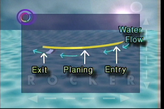
of planing board, be it a surfboard, the slalom sailboard or a racing longboard. In the case of the latter, an additional complication is that the rocker has to work across all of the board configurations- upwind sailing on the rail with the centreboard fully extended and the mast track forward and the sailor positioned in the upwind straps; downwind planing with the centreboard retracted, the mast track fully back and the sailor positioned in the tail straps; non-planning conditions, sailor's weight over the centreboard.

There is an interesting discussion on the UK sailboarding website Boards regarding the rocker of the Equipe-III from "GraemeF" who seems to have some experience with this issue. To quote

".... It'll probably have a Euro rocker, they always do, it certainly wont have the benefit of the old Mistral rocker profile. Complicated things Long board rockers, it's a three stage rocker.

Half the reason for the long track is using it to transition rocker stages, if they have mad(e) it with the track way back it's because they're using a flat straight rocker, good up wind, O.K. on Euro lakes, but totally useless on the sea.

The reason the current Equipe or Pan Am is still so successful these years later is because of the rocker. "

So the Euro rocker is designed for flat lakes and the Mistral rocker is designed for choppy/open sea c
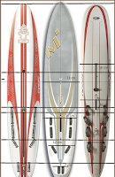
onditions. Given the comments of GraemeF, it's informative to consider a plan view of the Starboard Phantom 380, the Equipe-III and the Exocet Warp-X (see the figure). When comparing the Phantom 380 and Equipe-III you can see that there is quite a marked difference between the locations of board components. In particular the mast track front end terminates 21 cm further back on the Equipe, the centreboard is located 11 cm further back and the reaching straps are positioned 12 cm further back.

The differences are even more marked in the case of the Warp-X which has all components located closer to the bow, even when compared to the Phantom. I'd hazard a guess that the rocker of the Phantom and Warp-X may not be significantly different and that the placement of the components on the latter are also influenced by the removable tail fixture.

The comparisons shown in the figure seem entirely consistent with GraemeF's posting and if nothing else, demonstrates the importance of matching component location with rocker characteristics.

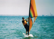
The majority of my sailboarding will be taking place on Port Phillip Bay at Elwood sailing club. For any sort of onshore wind conditions (which includes bay- and sea breezes), the area builds up a steep chop. Given this, my board will be constructed with a three part rocker which is consistent with these conditions. The following plot shows the normalised rocker (normalised by board length) which I am intending to use. I've derived this by looking at images of boards on the web and by measuring up a couple of older boards which I have access to. Also shown, for comparison is the normalised rocker of an older and slightly shorter board which was developed for flatter conditions.


You can see by comparing the two profiles that there is a significant amount of additional rocker required for ocean-going conditions.

All the best for now.

Sunday, August 10, 2008

Pieces in the puzzle

It's good news with StyraPak getting back to me and indicating that they can cut 2-d patterns in foam blocks. All I need to do is supply a .dxf file (preferably) or a suitable technical diagram. Looks like all that effort put into climbing up the learning curve with Sketchup may pay off, with dxf files being one of the outputs of the pro-version of this software. Hopefully the longitudal direction (which includes the rocker) of the longboard design can be included as one of the two dimensions that StyraPak can put on their cutting jig. Just need to finalise the shape now so that StyraPak can quote a price.

In the last posting Shapers Australia was mentioned as being a good one-stop shop with pretty much all of the materials required to build the longboard. One thing that caught my eye was a set of DVDs featuring tutorials from some of the top guys in the surfing scene in the areas of shaping and glassing boards. So I lashed out and ordered Shaping 101 (took me back to those hazy days doing Maths and Physics 101 at Uni) by John Carper, a guy who seems to be pretty well known in surfing circles (i.e. check out the following interview in TransWorld Surf). Haven't had time to check out the entire DVD as yet, but it does appear to be full of good practical advice with respect to board shaping, and I've already learned a lot.

I just love how the years of surfboard shaping has made John Carper so skillful yet so casual. Here he is introducing one of his high tech cutting tools know as the hand saw. He then proceeds to demonstrate how you cut out a board outline in 20 seconds flat- no hesitation and perfectly square. I'll be sticking to that old adage measure three times and cut once- slowly.

The goal now is to have a first design put together over the next couple of weeks. At this stage the materials are firming up as H-grade polystyrene foam; 6 oz glass on the top and bottom with a layer of carbon fibre over the working area of the board (i.e. from the tail to the tacking area in front of the mast track; carbon fibre tape over the remainder of the rails and nose; marine ply (thin) reinforced with glass for the centreboard case; foam+carbon fibre for the centreboard; tuttlebox for the fin (not sure whether to build the fin as yet or to purchase) ; and perhaps something innovative (and drawn from dinghy sailing equipment) for the mast track.
Bye for now.

Monday, July 21, 2008

Foam Blanks

The last time (way back when), that I built a board, the sourcing of materials was dead easy. Basically you went polyurethane for the blank and e-glass/polyester for the shell and that was it. The task was also simplified because it was a short-board hence no centreboard, the mast base was fixed and consisted of a finbox and the blank was small enough to fit within the standard repertoire of a surfboard maker- and so was easy to purchase.

The longboard racer is a different ball game.

Not only has the choice of materials increased, but now it is necessary to deal with a sliding mast track system, a fully retracting centreboard and a board length beyond that of even a surfer's stand-up paddle board. The latter makes the purchase of a blank+stringer directly from a surfboard manufacturer more difficult. Additionally, it now appears that expanded polystyrene or extruded polystyrene are the materials of choice for the blank. A good introduction with respect to these materials can be found at Fibreglass Supply

After some searching, I've been able to source some blanks of a suitable size. Shapers Australia is a good possibility for people who live in Queensland Australia, not only having blanks, but also appearing to be a one-stop shop for most of the other materials required to build a board. Unfortunately I have not found a surfboard manufacturer in Victoria who can supply a blank with stringer of the required size. However, Polyfoam Australia have high density (24 g/l) EPS blocks of dimension 500cm x 120 cm x 60 cm which can be cut down to a suitable (rectangular) size. And, wonder-of-wonders- a sister company StyraPak P/L can supply computer cut blocks of EPS or the higher density XPS. The computer-cutting capability presumably means that they could cut a rocker into the block and potentially save heaps of elbow grease and some of the agonising during the shaping stage. I've just emailed StyraPak and am waiting to hear back. Stay tuned!

Sunday, July 13, 2008

Working on the fundamentals

Thank-you rob134 for the encouraging comments and the 'Crownie' challenge. Thank-you Pat for the offer of help in the board design and the chance to contribute to a blog on LBWS. It's great to see that some Starboard Phantom 380s have made it to Australia.

The last couple of weeks has been spent working on some of the basic requirements of the board building project. This has included board design, coming up to speed with software for drafting the board design, and researching and sourcing the best materials for board construction. Although this is all very much work in progress, it's probably worthwhile getting these ideas out into the blogosphere.

Board Design
It seems to me that board design may be predicated on the following.
  1. If the wind speed is light enough for pumping to dominate board speed- particularly upwind, then basically the fastest sailboarder will be the one with the highest strength to weight ratio and small variations in board shape are probably not significant.

  2. For wind speeds above the 'pumping regime' and barring big variations in average board speed downwind due to wipe-outs, upwind board speed is probably the dominant factor in determining who it going to make it around a course in the shortest time. Of course in making this statement I'm thinking sailboat courses and equilateral triangles- not sausage courses!

  3. My experience (from a few years back now so it may be a little out of date) is that you basically go for the biggest centreboard possible for maximum railing and pointing under marginal conditions. In stronger winds, you take advantage of the fact that the railing 'moment' is pretty sensitive to the centreboard angle of rake, and so it is possible to de-power the board as the wind speed increases by raking the centreboard back. This also has the advantage of enabling you to stand further back on the board.

  4. Sharp straight rails in the forward half of the board would seem to be the way to go for optimal upwind performance. The compromise to avoid digging in and wiping out downwind is to have some rocker and softening of the rails towards the nose of the board.

  5. Maximum board width sounds like a good idea for early planing, and perhaps for increased power going upwind. Here I'm thinking back to some limited experience in 14ft skiff sailing and the need to move away from the centreline to increase righting moment.

  6. It seems a good idea to have a concave shape on the underside of the board, extending from the bow and terminating somewhere near the centreboard case (are single or double concaves better?). It is envisaged that a concave shape will minimise wetted area when railing upwind, and will provide additional lift when planing downwind. The downside is that there will be more wetted area in displacement conditions- but here it is expected that power-to-weight ratio will dominate anyway as discussed in (1).

  7. Flat bottom with some rocker in the back half of the board and a nice big fin which doesn't cavitate for good downwind performance in planing conditions. The latter is to avoid those catastrophic wipe-outs downwind as mentioned in (2).

  8. It would be nice to have a narrow tail for demonstrating that carve jibes are possible on a longboard- however a wider tail (i.e. Phantom 380) may be preferable for earlier planning in marginal conditions, and for planning at deeper angles downwind (Starboard promotes this design feature with the 380).
That's it on board design for now. Be interesting to get some feedback.

Google SketchUp
This is an example of a nice little package for constructing 3-D models. I think it's mainly promoted by Google as a package for constructing buildings and other objects for embedding into Google Earth (i.e. check out New York with the building layer enabled and you'll get the idea).

The package appears to easily have the capability to draft up a longboard design. This is demonstrated (at a very basic level) below where I've taken a plan view of the Exocet Warp-X and constructed a simple scale model using the line and arc drawing tools. Note that the intention is not to copy the design of the Warp-X, nor any other contemporary longboard design. At this stage I'm just using the Warp-X as a model to help build up the requisite skills with Sketchup.


Construction Materials
I've been trawling through some of the surfboard manufacturers websites trying to come up to speed with surfboard construction techniques where they appear applicable to the construction of a sailboard. More on this in the next Post.

Saturday, June 28, 2008

A beginning

I've been looking to get back into sailboarding following a break of more than 10 years. When I left the sport, my sailing club (Elwood Sailing Club near Melbourne Australia) had regular Saturday afternoon longboard racing on sailing courses which we shared with the dinghy's. It was a popular activity, usually with 10-20 sailboaders turning up each week. There were a couple of really good sailors and the result of us were in it for the fun and the challenge of actually finishing.

However, over the intervening years this form of the sport appears to have largely died out, perhaps due to cost, perhaps due to the introduction of the Formula class; perhaps due to the invention of kite-sailing; or maybe because of the popularity of computers and home theatre systems?

However, it would appear that a resurgence in the sport may be underway with some of major sailboard manufacturers now producing racing longboards. Notable amongst these is the Exocet Warp-X by Kona Windsurfing and the Phantom 380 by Starboard Products. The Phantom Race 380 looks like a particularly good board, having won the 2007 RaceBoard World championships fairly convincingly.

I've looked into purchasing either of the Warp-X and Phantom Race, but both, unfortunately lie outside of my current budget, particularly when you factor in the cost of the rig (I'm starting from scratch, having sold all of my old gear off a decade ago to make a house repayment!). Additionally, both boards are difficult to get in Australia at the current time although delivery of the Warp-X does appear less problematic. Apparently only two Phantom Race boards are being made available for the Australian market this year (maybe). In this regard, I'm led to understand that some positive souls put a deposit down on a 380 last year and no deliveries were made.

Because of my limited budget, and because of the apparent delivery difficulties, I have decided to build a raceboard from scratch. This is done with the knowledge that such a board will not be ISAF registered and thus cannot formally race against other modern longboards. To be honest I don't think this is an issue for the next sailing season, because it is basically going to be me against the sailing dingies and perhaps one or two sailboarders who might be convinced to dust off their old raceboards and have a sail. In any event, half of the fun will be designing and building the board.

So that is an introduction to what I'm intending to do. The next stage is to research the best board design and the best (and most practical) construction techniques.

Wish me luck!